
Monitoring Optics: Reading Light Levels Before Links Die
Fiber links have a reputation for dying suddenly — fine at lunch, dark by dinner — and the reputation is mostly slander. What actually happens, far more often, is a slow fade. The light arriving at one end weakens over weeks or months. Errors begin trickling in as the signal approaches the receiver's limits. Then one day the signal finally slips below the level the hardware can decode. The death is sudden. The dying was measurable the whole time.
Measurable — because nearly every modern optical transceiver contains its own set of sensors. On request, it will report exactly how much light it is sending, how much it is receiving, and how it is feeling. Most admins never ask. This guide teaches you to ask. It covers what the transceiver's numbers mean and how to read power levels in dBm without a physics degree. It covers what healthy margins look like, and why a gradual receive-power decline is the single best pre-failure warning in networking. And it covers how to poll it all automatically. That way, a fading link becomes a calm maintenance ticket instead of a dead uplink at the worst possible hour.
In this guide
- Transceivers in plain language
- The sensors inside: digital optical monitoring
- dBm without tears
- The classic pre-failure story: the slow fade
- The usual suspects
- Four numbers, one verdict: diagnosing by direction
- Polling over SNMP and alerting on trends
- Clean it or replace it?
- Where to go next
Transceivers in plain language
A transceiver — the small metal module you plug into a switch port, often just called an optic — is a translator. On its electrical side it speaks to the switch. On its optical side, a tiny laser turns outgoing data into pulses of light. A photodiode (a light sensor) turns arriving pulses back into electrical signals. Fiber links are built from two one-way light paths. Your transmitter shines down one strand into the far end's receiver. Their transmitter shines back down the other strand into yours. Keep that picture — two independent one-way beams — because half of optical troubleshooting is just asking "which beam is weak?"
Transceivers come in many speeds and reach classes. Short-range modules serve a run across the server room, while long-range ones can push light across town. But they share the same anatomy and, luckily for us, the same self-awareness. The fiber itself comes in two broad families you'll hear named constantly. There is multimode, with a wider core, used for shorter in-building runs. And there is single-mode, with a far narrower core, used for long hauls and increasingly for everything else. The practical rule is simply that the module, the fiber type, and the far end must all be from matching families. A mismatch delivers weak or no usable light even when every component is individually healthy. It's a classic explanation for a brand-new link that reads starved on day one.
One more framing before the sensors: transceivers are, frankly, the physical layer's most honest component. A copper cable suffers in silence and must be interrogated with testers and swap games. A transceiver can simply be interviewed, any time, from your desk. This guide is essentially a course in asking it good questions.
The sensors inside: digital optical monitoring
The interview mechanism goes by a few names — digital optical monitoring (DOM), digital diagnostics monitoring (DDM) — but the idea is the same everywhere. The module continuously measures a handful of values and exposes them to the switch. The switch exposes them to you, on the command line and over SNMP. The values that matter:
Transmit power: how loudly you're shouting
The strength of the light this module's own laser is emitting, measured in dBm (explained shortly). It should sit comfortably in the module's specified range and barely move for years. A slow decline in transmit power is a laser aging toward retirement; an abrupt drop or wild instability means the module is failing now.
Receive power: how loudly the far end reaches you
The strength of the light arriving from the other end, after every connector, splice, patch cord, and meter of glass has taken its toll. This is the most valuable single number in optical monitoring, because it summarizes the health of the entire incoming path in one reading. Too little light and the receiver starts guessing (errors), then gives up (link down). Too much light is also possible on very short runs with long-reach optics. A receiver can be overdriven like an ear next to a loudspeaker. That is why installers sometimes add attenuators, deliberate light-dimming elements, to bring the level into the comfortable middle.
Temperature: how hot the module is running
Lasers age faster hot, and a module baking in a poorly ventilated switch runs closer to misbehavior. A rising temperature trend usually indicts the environment — blocked airflow, a failed fan, a crowded rack — before it indicts the module. Watch it the way you'd watch any equipment temperature: for drift away from its own normal.
Voltage and bias current: the vital signs
Supply voltage is the electrical feed the module receives. It should be boring, and any real movement points at the switch's port hardware rather than the fiber. Laser bias current — reported by many modules — is subtler and wonderful: it's how hard the module is driving its laser to achieve the target transmit power. As a laser wears out, the module quietly compensates by driving it harder. So rising bias current with flat transmit power is the sound of a module pedaling harder to hide its age. That is one of the earliest failure predictions you can get from any hardware, anywhere.
dBm without tears
Optical power is measured in dBm: decibels relative to one milliwatt of power. It's a logarithmic scale, which sounds intimidating and is actually a kindness — it turns the multiplication of losses into simple addition. You only need three facts. Zero dBm means exactly one milliwatt. Every 3 dB down means half the power. Every 10 dB down means one tenth. That's it; everything else is arithmetic:
| Reading | Actual power | Plain English |
|---|---|---|
| 0 dBm | 1 milliwatt | The reference point |
| -3 dBm | 0.5 milliwatt | Half the reference |
| -10 dBm | 0.1 milliwatt | A tenth — still plenty for many receivers |
| -20 dBm | 0.01 milliwatt | A hundredth — getting quiet |
| -30 dBm | 0.001 milliwatt | A whisper — below most receivers' hearing |
So negative numbers are completely normal — nearly all healthy receive readings are negative — and "more negative" means "less light." A link's life story in dBm is simple bookkeeping. The transmitter launches at some level. Every connector and splice subtracts a fraction of a dB, and every stretch of glass subtracts a little more. Whatever remains arrives as receive power. The gap between that arriving level and the weakest signal the receiver can decode (its sensitivity floor) is your margin. That is the budget you can afford to lose to dust, aging, and entropy before the link fails.
What counts as healthy? It genuinely varies by module type and reach class, which is why the honest answer beats a memorized one. Here it is: every DOM-capable module carries its own factory-programmed warning and alarm thresholds for each value, high and low. It reports them right alongside the readings. Those thresholds are the authoritative numbers for that module. As a feel for scale: a receive level around -5 to -10 dBm is comfortable for many common short-reach modules. A low-warning threshold might sit somewhere near -18 dBm, and the alarm floor a few dB below that. But read yours, don't quote this paragraph at them. Your working rule: know your margin, and get nervous when it shrinks toward a couple of dB.
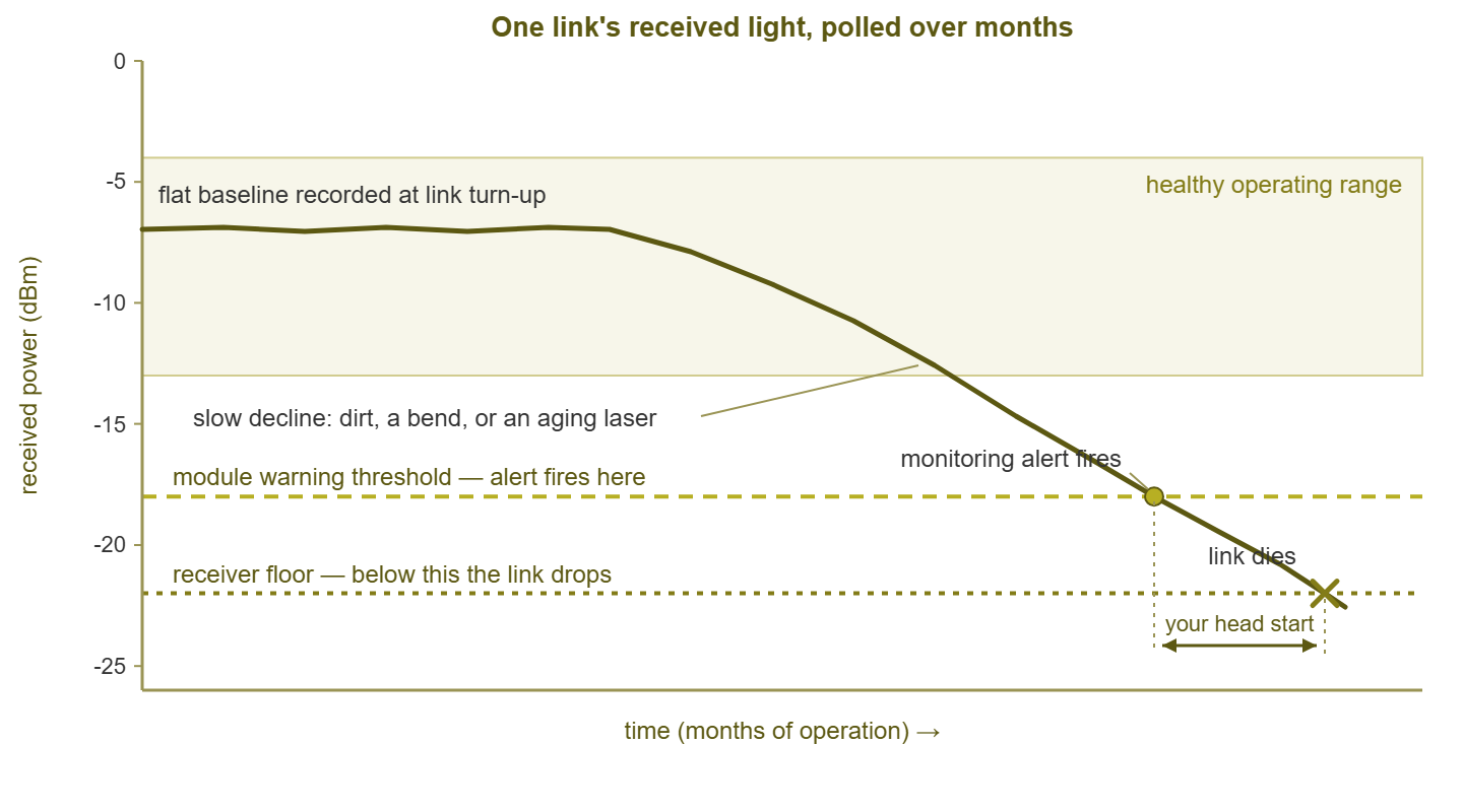
Figure 1: The slow fade. Receive power declines gradually and crosses the warning threshold long before the receiver floor. The gap between those two crossings is repair time you get for free — if something is watching.
The classic pre-failure story: the slow fade
Now the story the figure tells, because it is the story of optical failure. A link is installed and comes up with, say, a comfortable receive level and a fat margin. Months pass. Dust works its way into a connector; a patch cord gets nudged into a tighter bend during unrelated closet work; the far laser loses a little strength to age. Each insult subtracts a fraction of a dB. The link keeps working perfectly — margins exist precisely to absorb this — so nothing visible happens. The decline is silent, slow, and utterly invisible to anyone who isn't recording the number.
Eventually the level approaches the receiver's limits, and the first symptoms appear: occasional CRC errors on that interface. That is the marginal-medium pattern where errors scale with traffic (the error counter field guide shows you exactly what that looks like). Then errors thicken, then the link starts flapping, and finally it drops for good. And the outage report will say the link "suddenly failed," which is true in the same way a car "suddenly" runs out of fuel. The flapping stage is especially cruel if nobody is watching the light. A link that's up again by the time you look leaves no visible evidence. That is precisely the trap described in why intermittent problems are hard. Meanwhile the receive-power graph, for anyone recording it, explains the whole haunting in one glance. The entire point of optical monitoring is captured in the figure's annotated gap. The decline crosses the warning threshold weeks or months before it crosses the floor. Everything between those two crossings is a head start that costs you nothing but a poll.
The usual suspects
Dirty connectors top the list, and it isn't close. The light in single-mode fiber travels through a glass core far thinner than a human hair. A speck of dust that would embarrass nobody on a shelf can eclipse a meaningful fraction of that beam. A fingerprint's oil film is a fog bank. Every time a connector is unplugged it's an opportunity for contamination. That is why receive levels so often step downward right after closet maintenance, and why "who re-patched something recently?" is a legitimate diagnostic question.
Bent and pinched fiber comes next. Light stays inside the glass by reflecting along it. Bend the fiber too sharply and some light literally leaks out at the bend and keeps going in a straight line, never to return. A patch cord crushed by a rack door, cinched by an enthusiastic cable tie, or forced around a tight corner can shed dB while looking perfectly intact. Unlike dust, a bend often announces itself as a sudden small step down in receive power dated to the day someone worked in that closet.
Aging lasers provide the truly gradual fades: transmit power drifting down over months, bias current drifting up as the module compensates. And a rotating cast of minor villains fills out the lineup. There are low-quality or damaged patch cords, and mismatched fiber types between panels. There are connectors seated almost-but-not-quite, and overheating modules whose readings wander. Note what's absent: sharp copper-style failures. Optical problems overwhelmingly show up as light-level arithmetic, which is why the numbers diagnose so much from a chair.
Four numbers, one verdict: diagnosing by direction
Because a fiber link is two one-way beams, four power readings describe it completely: your transmit and receive, and the far end's transmit and receive. Collect all four and the fault localizes itself:
| Pattern | Verdict |
|---|---|
| Far end transmits fine, but your receive is low | Loss in the path toward you: connectors, patch cords, splices, a bend |
| Your transmit is low at the source | Your module's laser is weak or dying — replace your module |
| Both directions arrive low | Shared path element: a dirty panel coupling, a crushed dual-strand cord |
| All four readings healthy, yet errors persist | Light level isn't the villain — suspect the module electronics, the port, or move up a layer |
Compare each number to the module's thresholds and to its own recorded baseline. And remember the subtraction: far transmit minus your receive equals the loss of the path between. That number should stay constant for the link's whole life. When that loss figure grows, the path degraded; when transmit itself sags, the source degraded. Two subtractions, and you've often localized the fault to one end of one beam before anyone touches a ladder.
Polling over SNMP and alerting on trends
Interactively, most switches print the whole interview with a command along these lines:
Switch# show interfaces gi1/1/1 transceiver
          Temperature  Voltage  Bias     Tx Power  Rx Power
Port      (Celsius)    (Volts)  (mA)     (dBm)     (dBm)
Gi1/1/1   41.3         3.29     6.1      -5.2      -7.9
That's a one-time reading; the payoff comes from collecting it forever. Most platforms expose the same values over SNMP. The exact location varies by vendor (entity-sensor tables or vendor-specific extensions). So expect a few minutes with your platform's documentation or an SNMP browsing tool to find them. And lean on the SNMP monitoring guides if that's new territory. Once found, poll them like any other metric. Every five minutes is plenty for values that move over weeks. Layer three kinds of alerts on top:
- Threshold alerts: warn when any value crosses the module's own warning threshold, alert on alarm thresholds. This is the safety net that catches every fade eventually.
- Trend alerts: compare today's receive power against the recorded baseline and flag a drop of more than a dB or two, even while still "healthy." This is the early-warning system — the one that buys you the head start in the figure.
- Change-after-maintenance checks: after any closet work, compare every optical reading on affected paths against the day before. A fresh step-down says a connector came back dirty or a cord came back bent, while the culprit's memory is still warm.
If you can't monitor every optic at once, triage by blast radius. In that case, focus on the uplinks between switches and anything crossing between buildings or floors. Riser and outdoor fiber lives a harder life than patch cords in a rack. Include the handoffs to your internet or WAN providers. Those are the links whose slow fade takes a whole site down — and, conveniently, the ones where the "free head start" is worth the most.
Tip: record the baseline the day a link turns up — all four power readings, plus the computed path loss — in your documentation. Thresholds tell you when a value is bad; only a baseline tells you when it has changed. A link reading -9 dBm is fine in the abstract and deeply suspicious if it read -5 at turn-up.
Clean it or replace it?
When low light is confirmed, the repair decision follows the direction logic. If the far transmit is healthy but arrival is weak, the path is lossy. In that case, the first move is almost always cleaning. Dirty connectors cause the bulk of path loss. Cleaning is cheap, and it's non-destructive. Do it properly — with purpose-made fiber cleaning tools, never a shirt cuff or canned air alone. Follow the ritual the fiber trade drills into apprentices: inspect, clean, inspect again. Use an inspection scope if you have one. Apply the ritual to both the patch cord tip and the port it mates into, at both ends of the suspect segment. Then re-read the levels. A good cleaning shows up instantly as recovered dB, which is one of the more satisfying before-and-after moments this job offers.
Reach for replacement instead when the evidence points at hardware. That evidence might be transmit power low at its source, bias current climbing quarter over quarter, or temperature alarms. It might be readings that jump erratically, or a module that has already been cleaned around and still fades. Transceivers are consumable parts — sockets exist so they can be swapped. So keep tested spares for every module type you run, and treat a swap as a five-minute experiment. If a known-good module reads healthy in the same port and path, the old module was the patient. If the new one reads just as starved, the path is. Then you're back to patch cords and panels — where the methodical one-change-at-a-time discipline from the cable plant guide applies to glass exactly as it does to copper. Bends, meanwhile, cost nothing to fix but a gentler re-routing — just re-dress the cord and watch the number recover.
Where to go next
You now know fiber's open secret. The hardware announces its own death months in advance, in a language of small negative numbers, to anyone polling. Set up the polls, record baselines, alert on trends, and the "sudden" fiber failure mostly exits your life. The companion skills live nearby: the error counter field guide covers the error patterns a starving receiver produces. And the symptoms guide shows how those errors masquerade as software problems. And the rest of the series waits at Finding Physical-Layer Problems.
Put this into practice with SysPeep Monitor
A fading optic gives you months of warning — but only if something polls the light levels and remembers the baseline. Where your switches expose transceiver diagnostics over SNMP, SysPeep Monitor can collect them on a schedule alongside your error counters and link status. In that case, it can graph the trends and alert on thresholds so the slow fade becomes a planned fix. The free trial installs on any Windows machine in minutes.
Download Free TrialLearn About SysPeep - All Rights Reserved.